|
|
| Safety Light Curtains with Blanking features |
BLVT |
|
| |
|
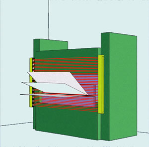
The
safety light curtains BLVT designed especially for their use as
protection devices at hazardous sites and areas, as well as pedestrian
access. By the use of the blanking features, moving or stationary
objects can be blanked.
BLVT provide the prevention of bodily injuries of fingers, hands, and limbs, e.g. when working at:
- raw material converting presses operated in the metal, wood, plastic, rubber, leather, glass industry
- filter presses
- folding and bending machines
- die-casting machines
- processing lines and welding presses
- insertion machines
- robots
- palletizers
back to Feissler Safety Products
|
protection at press brakes |
|
|
| |
|
The
safety light curtains ULVT are electrosensitive protective devices
(EPSE) and are characterized by compliance with safety category 4, EN
954-1 and IEC 61496, parts 1 and 2, i.e. EN 61496. |
|
- Blanking features for blanking any obstacles in the detection field
- integrated switching unit, contactor control and restart interlock activated by Dip-switches
- can be connected directly to contactors/valves, switching capacity 0,5A/24V
- minimum safety distance due to short response times, between 5 ms and 25 ms, depending on constructional length
- detection of smallest obstacles (14 mm / 30 mm) inside a detection range of 7 meters / 24 meters
- between 7 and 247 beams with protective heights from 100 up until 2500 mm
- micro-processor controlled safety functions
- muting and stroke operation with optional safety control-unit PLSG
- self-monitoring semiconductor outputs with line interruption monito ring, short-circuit- and side current passages check
- built-in self-diagnosis with error display
- protective system IP 65 (waterproof sealed)
|
| |
|
| |
The
transmitter generates infra-red light beams flashing at high speed in
synchronous action. The parallel light beams with a spacing of 7,5mm or
14,3mm are monitored by miocro-controllers. The receiver evaluated the
arriving beams in synchronous action to the transmitter.
Due to the closeness of the beams, a resolution of 14 mm / 30 mm is
achieved. If an obstacle is placed into the protective field, i.e. at
least iner lieght beam is interrupted, the hazardous movement of the
machine is stopped, i.e. a new start is not possible. |
|
| |
Integrated connector plug in connector cover |
| |
The
standard equipment of the product series ULVT includes an extra flat
plug-in connection located in the connection lid. This lid may be
removed without disconnecting the cable. The housing itself remains
sealed.
Several custom-made connection plugs are available as options.
The transmitter is connected via a 3-core cable, the receiver is
connected via a 7-core-cable (according to the respective operational
function). |
|
|
|
Operating mode |
| |
DIP-position
Without contactor check |
DIP-position
With contactor check |
The operational mode with contactor control serves for monitoring of the triggered seconday contactors. After each
interruption of the beams and before each release of the outputs, it is
verified whether the secondary contactors have fallen. Only then
another release is possible. If there is no reaction by contactors
within 300 ms, the light curtain switches off the outputs and turns
into interruption/locked mode. |
|
|
|
DIP-position
Without restart interlock |
DIP-position
With restart interlock |
If
the operational mode with restart interlock is selected, a push-button
must be installed at the start button input in order to release the
start of the working movement.
With free protective field, the yellow receiver LED lights up, requesting operation start.
Only after pushing the start button both outputs of the ULVT are activated. |
|
|
|
DIP-position
Equivalent outputs |
DIP-position
Antivalen outputs |
During
the operational mode equivalent outputs both PNP-outputs are safety
outputs and provide short-circuit- and side-current passages
monitoring. With free optical path both outputs are high (+24V). During
the operational mode antivalent outputs, output No .1 is high (+24V)
and output No. 2 low (0V), with free optical path. During this
operational mode, output 2 does not provide fail-safe results. This
operational mode is only permitted if the safety control units LSUW NSR
3-1K, LSUW N1-Muting K or another safe secondary control to monitor
output No. 2. are applied! |
|
| |
technical data |
| |
| |
Transmitter ULVTS |
Receiver BLVTE |
| Supply voltage |
24V DC SELV, +20% -10% |
24V DC SELV, +/- 20% |
| Current consumption |
max. 250mA |
max. 250mA (without load) |
| Outputs |
- |
OSSD 1 and 2:
error-proof PNP outputs; max. 0,5A short-circuit and transverse conclusion monitoring
(in operating mode of antivalent outputs Output2 is not error-proof, max. 20mA) |
| Inputs |
- |
Inputs contactor control and start push-button: 0V to 24V DC + / - 20% |
| electrical link |
integrated plug connector with PG9 as strain relief;
alternatively usual market plug connectors |
integrated plug connector with PG9 as strain relief;
alternatively usual market plug connectors |
| Lead |
3-pol. max 1,5mm² |
5 to 7-pol. (depending upon type of driving) max. 1,5mm² |
|
|
additional functions |
|
| For
additional functions, like potential-free output contacts, stroke
operation or Muting, the optional safety switching units ULSG, LSUW NSR
3-1-K and LSUW N1-Muting K are available, as well as a special
programmer device for the Blanking program. |
| |
Executions |
| |
|
| |
| |
|
resolution 14 mm |
resolution 14 mm |
resolution 30 mm |
resolution 30 mm |
Protection box height (mm)
/ ray number |
Construction length (mm) |
Order data |
reaction time (ms) |
Order data |
reaction time (ms) |
100 / 13 |
196 |
BLVT 100 / 13 |
7 |
BLVT 100 / 7 |
7 |
200 / 26 |
296 |
BLVT 200 / 26 |
9 |
BLVT 200 / 14 |
9 |
300 / 39 |
396 |
BLVT 300 / 39 |
10 |
BLVT 300 / 21 |
10 |
400 / 52 |
496 |
BLVT 400 / 52 |
12 |
BLVT 400 / 28 |
12 |
500 / 65 |
596 |
BLVT 500 / 65 |
14 |
BLVT 500 / 35 |
14 |
600 / 78 |
696 |
BLVT 600 / 78 |
15 |
BLVT 600 / 42 |
15 |
700 / 91 |
796 |
BLVT 700 / 91 |
17 |
BLVT 700 / 49 |
17 |
800 / 104 |
896 |
BLVT 800 / 104 |
19 |
BLVT 800 / 56 |
19 |
900 / 117 |
996 |
BLVT 900 / 117 |
20 |
BLVT 900 / 63 |
20 |
1000 / 130 |
1096 |
BLVT 1000 / 130 |
22 |
BLVT 1000 / 70 |
22 |
1100 / 143 |
1196 |
BLVT 1100 / 143 |
24 |
BLVT 1100 / 77 |
24 |
1200 / 156 |
1296 |
BLVT 1200 / 156 |
25 |
BLVT 1200 / 84 |
25 |
1300 / 169 |
1396 |
BLVT 1300 / 169 |
27 |
BLVT 1300 / 91 |
27 |
1400 / 182 |
1496 |
BLVT 1400 / 182 |
28 |
BLVT 1400 / 98 |
28 |
1500 / 195 |
1596 |
BLVT 1500 / 195 |
30 |
BLVT 1500 / 105 |
30 |
1600 / 208 |
1696 |
BLVT 1600 / 208 |
32 |
BLVT 1600 / 112 |
32 |
1700 / 221 |
1796 |
BLVT 1700 / 221 |
33 |
BLVT 1700 / 119 |
33 |
1800 / 234 |
1896 |
BLVT 1800 / 234 |
35 |
BLVT 1800 / 126 |
35 |
1900 / 247 |
1996 |
BLVT 1900 / 247 |
37 |
BLVT 1900 / 133 |
37 |
|
| |
|
| |
|
Contact Extension:
The contact extension FSEM for the extension or contact reinforcement. Applications up to the category 4 after EN 954-1 can be realized. |
|
| |
| |
Download |
|
|
|
|
|
|
|
|
|
|
BLPG/BPSG |
Operating Instructions: Programming devices for BLVT |
|
|
- |
- |
- |
- |
- |
Muting |
Description of the Mutingfunktion of the guard light barriers |
|
- |
- |
- |
- |
- |
- |
BLVT |
Appliance descrition |
|
|
- |
- |
- |
- |
- |
BLVT |
|
|
|
- |
- |
- |
- |
- |
BLVT |
Supplementing operating instruction |
|
- |
- |
- |
- |
- |
- |
BLVT |
Dimensional drawings of XLVT 100-1900 in stp,igs,dxf,dwg
|
|
|
| |
|
|
 |