|
|
| |
|
- Prevention of bodily injuries of fingers, hands, and limbs, e.g. when working at:
- Raw material converting presses operated in the metal, wood, plastic, rubber, leather, glass industry
- Filter presses
- Folding and bending machines
- Processing lines and welding presses
- Insertion machines
- Robots
- Palletizers
back to Feissler Safety Products
|
|
| |
|
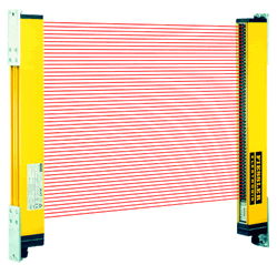
The
safety light curtains ULVT are electrosensitive protective devices
(EPSE) and are characterized by compliance with safety category 4, EN
954-1 and IEC 61496, parts 1 and 2, i.e. EN 61496. |
|
- integrated control-unit with contactor control and restart activatable by DIP switches activatable
- contactor/valves directly connectablly, switching capacity 0,5A/24V
- smallest safety distances by short response times 4,5ms to 24,5ms, depending of the protection high
- smallest obstacle recognition of 14mm from 0,3m to 7m range
- protection heights of 100mm to 1900mm in 100mm steps
- microprocessor monitoring of the safety functions
- built in selfdiagnostic with error display
- muting and stroke operation with optional safety control-unit PLSG
- protective system IP65
|
| |
|
| |
The
safety light curtains ULVT consist of the two components: transmitter
and receiver. The distance between both components and the overall
height result in those protection width and - height.
By the modular construction protection heights of 100mm to 1900mm are realizable. Special sizes are also available.
Transmitter
and receivers operate synchronously, i.e. at the same point in time
only a light beam and a reception item are active. The synchronisation
is made by the first light beam and the first reception item. Between
transmitter and receivers therefore no electrical connection is
necessary.
The transmitter creates infrared light
beams, which are switched on and off rapidly successively. The parallel
light beams with a distance from 7,5mm are controlled by two a chip
micro controllers. A resolution of 14mm is realised by the beam
distance.
Synchronously to the light beams of the
transmitter in the receiver all reception items are analysed by two a
chip micro controllers. If an object is in the protection field, i.e.
it is darkened at least one of the beams, the two outputs of the
receiver interrupt the dangerous movement of the machine, or prevent a
start. A renewed start of the machine is in the operating mode with
restart only possible by pressing the start push-button during a free
protection field.
Several LED at the receiver display
thereby the respective operating condition. The system detects an
internal or external error the machine is immediately switched off and
the LED in the transmitter or in the receiver shows by flashing the
error status. |
|
| |
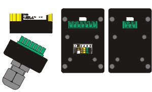
Integrated connector plug in connector cover |
| |
The
ULVT construction series is supplied with PG threaded joints as
standart. Various conventional connector plugs can also be obtained as
optional accessories. The electric connection is implemented via
terminal screws in the connector cover. The cover can be removed once
the 4 screws have been loosened. |
|
|
|
Operating mode |
| |
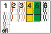
DIP-position
Without contactor check |
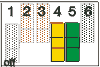
DIP-position
With contactor check |
The operating mode with contactor control serves for monitoring the triggered follow-up contactors.
After each interruption of the optical path and before each release of
the switching outputs the follow-up contaction are checked whether they
dropped. If the contactors don´t dropped with in 300ms the light
curtain output contacts go into lock status. |
|
|
|
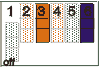
DIP-position
Without restart interlock |
DIP-position
With restart interlock |
If
the operating mode with restart control is adjusted, a push-button must
be connected for the start release of the working movement.
With a
free protection field the yellow LED lights up. After actuating the
start push-button the two outputs of the ULVT are activ. |
|
|
|
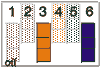
DIP-position
Equivalent outputs |
DIP-position
Antivalen outputs |
In
the operating mode bivalent outputs both PNP outputs are errorproof and
internally monitored on short circuit ad transverse. With free optical
path, both outputs are high (+24V). In the operating mode antivalent
outputs with free optical path output1 is high (+24V) and output2 is
low (0V). Output2 is not error-proof in this operating mode. This
operating mode is only allowed in connection with the control-units LSUW NSR 3-1K, LSUW N1-Muting K or another safe secondary control, which monitors the Output2! |
|
| |
technical data |
| |
| |
Transmitter ULVTS |
Receiver ULVTE |
| Supply voltage |
24V DC SELV, +20% -10% |
24V DC SELV, +/- 20% |
| Current consumption |
max. 250mA |
max. 250mA (without load) |
| Outputs |
- |
OSSD 1 and 2:
error-proof PNP outputs; max. 0,5A short-circuit and transverse conclusion monitoring
(in operating mode of antivalent outputs Output2 is not error-proof, max. 20mA) |
| Inputs |
- |
Inputs contactor control and start push-button: 0V to 24V DC + / - 20% |
| electrical link |
integrated plug connector with PG9 as strain relief;
alternatively usual market plug connectors |
integrated plug connector with PG9 as strain relief;
alternatively usual market plug connectors |
| Lead |
3-pol. max 1,5mm² |
5 to 7-pol. (depending upon type of driving) max. 1,5mm² |
|
|
Executions |
|
| |
|
14 mm |
14 mm |
30 mm |
30 mm |
Protection box height (mm)
/ ray number |
Construction length (mm) |
Order data |
reaction time (ms) |
Order data |
reaction time (ms) |
100 / 13 |
196 |
ULVT 100 / 13 |
6 |
ULVT 100 / 7 |
5 |
200 / 26 |
296 |
ULVT 200 / 26 |
7 |
ULVT 200 / 14 |
6 |
300 / 39 |
396 |
ULVT 300 / 39 |
8 |
ULVT 300 / 21 |
6 |
400 / 52 |
496 |
ULVT 400 / 52 |
9 |
ULVT 400 / 28 |
7 |
500 / 65 |
596 |
ULVT 500 / 65 |
10 |
ULVT 500 / 35 |
7 |
600 / 78 |
696 |
ULVT 600 / 78 |
11 |
ULVT 600 / 42 |
8 |
700 / 91 |
796 |
ULVT 700 / 91 |
12 |
ULVT 700 / 49 |
9 |
800 / 104 |
896 |
ULVT 800 / 104 |
13 |
ULVT 800 / 56 |
9 |
900 / 117 |
996 |
ULVT 900 / 117 |
14 |
ULVT 900 / 63 |
10 |
1000 / 130 |
1096 |
ULVT 1000 / 130 |
15 |
ULVT 1000 / 70 |
10 |
1100 / 143 |
1196 |
ULVT 1100 / 143 |
17 |
ULVT 1100 / 77 |
11 |
1200 / 156 |
1296 |
ULVT 1200 / 156 |
18 |
ULVT 1200 / 84 |
12 |
1300 / 169 |
1396 |
ULVT 1300 / 169 |
19 |
ULVT 1300 / 91 |
12 |
1400 / 182 |
1496 |
ULVT 1400 / 182 |
20 |
ULVT 1400 / 98 |
13 |
1500 / 195 |
1596 |
ULVT 1500 / 195 |
21 |
ULVT 1500 / 105 |
13 |
1600 / 208 |
1696 |
ULVT 1600 / 208 |
22 |
ULVT 1600 / 112 |
14 |
1700 / 221 |
1796 |
ULVT 1700 / 221 |
23 |
ULVT 1700 / 119 |
15 |
1800 / 234 |
1896 |
ULVT 1800 / 234 |
24 |
ULVT 1800 / 126 |
15 |
1900 / 247 |
1996 |
ULVT 1900 / 247 |
25 |
ULVT 1900 / 133 |
16 |
|
| |
|
| |
|
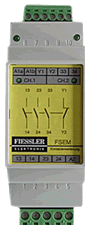
Contact Extension:
The contact extension FSEM for the extension or contact reinforcement. Applications up to the category 4 after EN 954-1 can be realized. |
|
| |
Download |
|
|
|
|
|
Muting |
Description of the Muting function of the guard light barriers |
|
- |
ULVT |
Appliance descrition |
|
|
ULVT |
|
|
|
ULVT |
Dimensional drawings of XLVT 100-1900 in stp,igs,dxf,dwg
|
|
|
| |